Why cant a Space Elevator be put in LEO?

Page 2 - Seeking answers about space? Join the Space community: the premier source of space exploration, innovation, and astronomy news, chronicling (and celebrating) humanity's ongoing expansion across the final frontier.
Status
Not open for further replies.
W

webtaz99

Guest
One thing this thread points out quite clearly, that many folks don't seem to realize:

We (the human race) are not short on ideas or dreams, just "political will". :(
 
M

MeteorWayne

Guest
HopDavid":3589leyc said:
neilsox":3589leyc said:
Mars can have an Edwards type space elevator, but not Venus due to it's very slow rotation and extremely hot surface.
The moons of the gas giant planets, Earth and Mars can have low cost Edwards type elevators passing though their L1, but they don't provide a lot of delta v.

Phobos has a healthy angular velocity and is in a steep part of Mars' gravity well. That means for a relatively short length of tether, it can provide substantial delta V
PhobosTether.jpg

You do realize that the image you presented is WAY out of whack compared to reality. Phobos' orbit would be on the outside
of the line describing Mars' atmosphere if that were accurate. Please find or create an accurate scale diagram.

And BTW, what dos this have to do with the subject of this topic, which is LEO (in case you forgot, that Low Earth Orbit)
 
H

HopDavid

Guest
MeteorWayne":1df0oyn6 said:
HopDavid":1df0oyn6 said:
neilsox":1df0oyn6 said:
Mars can have an Edwards type space elevator, but not Venus due to it's very slow rotation and extremely hot surface.
The moons of the gas giant planets, Earth and Mars can have low cost Edwards type elevators passing though their L1, but they don't provide a lot of delta v.

Phobos has a healthy angular velocity and is in a steep part of Mars' gravity well. That means for a relatively short length of tether, it can provide substantial delta V
PhobosTether.jpg

You do realize that the image you presented is WAY out of whack compared to reality. Phobos' orbit would be on the outside
of the line describing Mars' atmosphere if that were accurate. Please find or create an accurate scale diagram.

The red paths are orbits a payload would follow if released from a tether.

The path labeled "Mars Atmosphere" is an ellipse whose periapsis grazes Mars atmosphere. Perhaps it should be labeled "To Mars Atmosphere".

Mars atmosphere is indicated by a fine black line. If I recall correctly, I set that boundary 300 km above Mars surface. I show Phobos Orbit as being 5680 kilometers beyond that line.

MeteorWayne":1df0oyn6 said:
And BTW, what dos this have to do with the subject of this topic, which is LEO (in case you forgot, that Low Earth Orbit)

I was responding to Neilsox who wrote:
"Mars can have an Edwards type space elevator, but not Venus due to it's very slow rotation and extremely hot surface.
The moons of the gas giant planets, Earth and Mars can have low cost Edwards type elevators passing though their L1, but they don't provide a lot of delta v."

For your benefit I bolded part of his quote.
 
E

EarthlingX

Guest
Nice image, and thanks for your trouble with it :cool:

It is a bit of a topic, and i think it is my fault. Perhaps it is time for a new thread about Solar system elevators ?
 
N

neilsox

Guest
I'm not sure I understand space shaft, but let me try anyway. The top part needs to be small and light, or the bottom will rest on Earth's surface, probably before the top reaches 50 kilometers. We can use hydrogen for all but the bottom 10 kilometers or so, as hydrogen won't burn or explode above about ten kilometers altitude, because the air is too thin. We may not have enough helium even for the bottom 10 kilometers.
If the bottom ten kilometers displaces 100 tons of air, but weighs 90 tons, it can support 10 tons at higher altitude, plus perhaps one ton of buoyancy of the part above 10 kilometers. 11 tons maybe enough to reach to 50 kilometers, but more seems unlikely with our best materials we have at present. We need a means to climb inside or on the surface of this floating mountain. That will likely weigh about 11 tons, including a one tone pay load, so the floating mountain will start to descend at perhaps 2 kilometers per hour = its terminal velocity, due to air resistance. How can we get to the top fast enough to avoid the bottom 10 kilometers bouncing when it hits Earth's surface? It seems to me that the bottom ten kilometers needs to be anchored firmly to Earth's surface. Unfortunately that means wind storms will destroy the structure if it is anchored, as it has enormous wind loading. Did I miss something important? Neil
 
G

global_lift

Guest
Hello again,

There is much I have not written here about both the dynamics and the statics mentioned by Neil. And honestly it was not my intention to start at this time a discussion about the SpaceShaft since I'm preparing papers that specifically touch such points.

A few things I can say is there are:

* Indeed, the annual production of He is limited and if used for a SpaceShaft will leave other users without supply.
* The SpaceShaft uses mechanisms that do not require specific use of He to rise up to the height I am proposing. One hint at the potential is building sections underwater which will provide an increment 1000 fold greater due to water density. And I am sure you will agree with me that any industrial/military grade submersible can provide an enormous upthrust. Just consider semi-submersible construction barges which weigh not a few tons but are above a million.
* What I have described in this website is a very simple model. In reality the system will look a lot more like a telescopic system. Also I mentioned a balloon like ring but that was only for simplicity, in fact the structure has a special skeleton that makes the constituent buoyant sections behave as a rigid object. And anchoring , as you are surmising does exist but it is intended for other uses. For the issue of wind there are mooring lines, which are a completely separate system from the anchoring, and actually do take care not so much of wind and the CG at low Atm. altitude but the multiple center of buoyancy. As you point out weight becomes an issue after buoyancy has dissipated. Note that when balloons are designed to reach a specific altitude the first step is to calculate what is the required volume of atmosphere to be displaced taking into account the variables you mentioned. So a section of a SpaceShaft that is intended to reach a predefined altitude has to be calculated accordingly. The CG is likely to be located at elevations where the system is in a pure weight condition. At these elevations multiple sections, at specific intervals, will house gyroscopic systems to compensate for the deflections on the columnar sections. http://spaceshaft.org/noaa/wind/intro.html
* One major problem with the standard materials mentioned elsewhere for a small system, (Kevlar, Mylar, ... ,) is not so much with their strengths, which are Ok up to 100 km and beyond, but with their other properties being far more important since they are very susceptible to the space environment and will quickly degrade.

Neil, on a more personal side, yes you are missing somethings and there are quite a few you are not taking into account, but it is my fault and not yours. For a long time I had my website available to the public but this is not the case right now since I am remodeling the site. If you were to go there you will be redirected to another page with non-dynamic HTML so the actual calculations are not there but you will still be able to look at a selection of drawings that will hint at the actual solutions to the problems you have listed. http://spaceshaft.org or http://spaceentrepreneurs.ning.com/profile/NeslonSemino. The interactive 3D drawings are slow but I am sure they will be useful.

Non of the guys I spoke with (ISEC) have disproved the basics of my proposals, including B. Edwards. Neither did Prof. Quine at York Univ. who has his own proposal for an inflatable tower. http://ksjtracker.mit.edu/2009/07/01/sp ... had-known/

You will also see that there are other professionals involved in the endeavor, they started doing peer-review and have become actively involved.

I will try to respond to questions but I do not drop by that often to be a good member of the forum.

Thank you for the comments which I greatly appreciate and hope to keep getting.
 
H

HopDavid

Guest
HopDavid":1yh5r0jt said:
The path labeled "Mars Atmosphere" is an ellipse whose periapsis grazes Mars atmosphere. Perhaps it should be labeled "To Mars Atmosphere".

Mars atmosphere is indicated by a fine black line. If I recall correctly, I set that boundary 300 km above Mars surface. I show Phobos Orbit as being 5680 kilometers beyond that line.

I changed the labels. The red, atmosphere grazing ellipse formerly labeled "Mars Atmosphere" is now labeled "To Mars Atmosphere". The fine black line around Mars is now labeled "Mars Atmosphere".
 
H

HopDavid

Guest
MeteorWayne":12c1au0i said:
A LEO tether would have the tail end whipping by at ~ 16.500 mph above the surface, meanwhile encountering air and dragging the top end (satellite in LEO) down quite rapidly.

MW

Only a very poorly designed LEO tether.

I am uncomfortable with mph. I hope you don't mind if I call 16,500 mph 7.4 km/sec.

Earth's surface is moving about .5 km/sec at the equator. So an orbit moving 7.4 km/sec wrt earth's surface would have a speed of 7.9 km/sec.

An orbit having an altitude of 120 kilometers would be moving 7.9 km/sec.

This is an extremely bad place place to have the center of your tether. The tether's foot would presumably dip even lower. Such a tether certainly would be dragged down quite rapidly, as you say.

But LEO extends higher than 120 km. Some call any orbit under 2000 km a LEO.

A more sensible LEO tether would be centered higher. Say at a 800 km altitude. Such a tether would be moving at 7.4 km/sec at that altitude. But the foot would be moving slower. If you lowered the foot of the tether to a 300 km altitude, it would be moving at 6.9 km/sec. Which would be 6.4 km/sec relative to earth's surface, since the surface is moving .5 km/sec at the equator.

6.4 km/sec is about 15,500 mph.

At 300 kilometers and higher, the atmosphere might be tenuous enough that atmosphere wouldn't drag down the tether quite rapidly.
 
M

MeteorWayne

Guest
Since you have to get to within 1.5 km/s of LEO speed to catch the end of the tether, you have to accelerate most of the way to orbital velocity. So I really don't see much of a gain in efficiency.
(BTW, I prefer km/s myself :) )
MW
 
H

HopDavid

Guest
MeteorWayne":312hee8h said:
Since you have to get to within 1.5 km/s of LEO speed to catch the end of the tether, you have to accelerate most of the way to orbital velocity. So I really don't see much of a gain in efficiency.

Single Stage To Orbit Reusable Launch Vehicles (SSTO RLVs) were the holy grail for rocket engineers for the last 50 years or so. But no one has been able to close a design. A few of the major obstacles: Propellent mass ratio strongly presses for multi-stages. Also re-entry is extremely abusive. Via aerobraking, the shuttle loses 8 km/sec in about an hour. This mandates thermal protection, wings and lots of massive and failure prone stuff.

Rocket Equation

The rocket equation gives this quantity for ratio of propellent mass to mass delivered to orbit:

e^(dV/Ve) - 1

Where
e is about 2.72
dV is delta V needed
Ve is exhaust velocity

If I remember right, one of the better chemical propellents is oxygen and hydrogen with an exhaust velocity of 4.4 km/sec

Let's take a look at what a difference of 1.5 km/sec does to mass ratio.

e^(9.5/4.4) - 1 = 7.66
e^(8/4.4) - 1 = 5.16

Nearly a 33% reduction in propellent mass needed for a given payload.

Re-Entry

Now let's look at re-entry abuse. Kinetic energy is 1/2 m v^2. The mass in that quantity is volume of air encountered times density. Now the voume encountered per second is vehicle cross section area times velocity. So atmospheric re-entry abuse scales roughly with velocity cubed.

(6.5/8)^3 = .53

In summary:
Needed propellent mass is reduced by about a third. Thermal and other atmospheric abuse is reduced by nearly half.

This would make for a whole new set of minimum requirements. Meeting these would be more doable.

I think it's quite possible a tether that cuts 1.5 km/sec could enable SSTO RLVs.

MeteorWayne":312hee8h said:
(BTW, I prefer km/s myself :) )
MW

It's a lot more sensible.

Do the revisions to the Phobos Tether labels make the illustration more acceptable?
 
M

MeteorWayne

Guest
HopDavid":30ef01bx said:
Do the revisions to the Phobos Tether labels make the illustration more acceptable?

Well, still not technically LEO (after all the E stands for earth :) ) but I don't want to crush discussion... you made a decent case for keeping it here :D Thanx
MW
 
N

neilsox

Guest
~Hi global_lift » Fri Jun 11, 2010 8:40 am My coments are enclosed with~
SpaceShaft
* Indeed, the annual production of He is limited and if used for a SpaceShaft will leave other users without supply.
* The SpaceShaft uses mechanisms that do not require specific use of He to rise up to the height I am proposing. One hint at the potential is building sections underwater which will provide an increment 1000 fold greater due to water density. And I am sure you will agree with me that any industrial/military grade submersible can provide an enormous upthrust. Just consider semi-submersible construction barges which weigh not a few tons but are above a million. ~true but the the portion just above the water level needs to support nearly all the weight above about 10 kilometers~
* What I have described in this website is a very simple model. In reality the system will look a lot more like a telescopic system. Also I mentioned a balloon like ring but that was only for simplicity, in fact the structure has a special skeleton that makes the constituent buoyant sections behave as a rigid object. And anchoring , as you are surmising does exist but it is intended for other uses. For the issue of wind there are mooring lines ~in very deep water, each mooring line can be attached to ship which allows the base to be moved to recover balance if the lean becomes excessive due to winds, human error or partal failure of the whole assembly. Locating at the Brad Edwards sweet spot in the South Pacific would greatly reduce the wind, storm and lightning problems~ which are a completely separate system from the anchoring, and actually do take care not so much of wind and the CG ~Do the letters CG stand for center of gravity?~ at low Atm. altitude but the multiple center ~How can there be a multiple center?~ of buoyancy. As you point out weight becomes an issue after buoyancy has dissipated. Note that when balloons are designed to reach a specific altitude the first step is to calculate what is the required volume of atmosphere to be displaced taking into account the variables you mentioned. So a section of a SpaceShaft that is intended to reach a predefined altitude has to be calculated accordingly. The CG is likely to be located at elevations where the system is in a pure weight condition. At these elevations multiple sections, at specific intervals, will house gyroscopic systems to compensate for the deflections on the columnar sections. http://spaceshaft.org/noaa/wind/intro.html
* One major problem with the standard materials mentioned elsewhere for a small system, (Kevlar, Mylar, ... ,) is not so much with their strengths, which are Ok up to 100 km and beyond, but with their other properties being far more important since they are very susceptible to the space environment and will quickly degrade. ~You must be thinking square kilometers near the base (large taper) to get to 100 kilometers with a material weaker than diamond~

Neil, on a more personal side, yes you are missing somethings and there are quite a few you are not taking into account, but it is my fault and not yours. For a long time I had my website available to the public but this is not the case right now since I am remodeling the site. If you were to go there you will be redirected to another page with non-dynamic HTML so the actual calculations are not there but you will still be able to look at a selection of drawings that will hint at the actual solutions to the problems you have listed. http://spaceshaft.org or http://spaceentrepreneurs.ning.com/profile/NeslonSemino. The interactive 3D drawings are slow but I am sure they will be useful.

None of the guys I spoke with (ISEC) have disproved the basics of my proposals, including B. Edwards. Neither did Prof. Quine at York Univ. who has his own proposal for an inflatable tower. http://ksjtracker.mit.edu/2009/07/01/sp ... had-known/
~Now I picture the under water portion a 2 kilometer diameter segment of a cone with a one kilometer hole, into which the 2nd level, mostly above water section telescopes into, thus allowing a vertical adjustment, and a buoyancy adjustment. Perhaps 20 columns in a 0.99 kilometer circle stand on the circumference of the 2nd section. Each column is one kilometer tall, and telescopes into a larger diameter column, at a higher (but adjustable) altitude. I suppose we can alternate large hollow and smaller gas filled columns all the way to 100 kilometers with the telescope fully extended, and shorten the assembly when a hurricane threatens and as a pay load climbs the tower. With excellent timing, perhaps the telescoping sections will bounce as they reach the minimum height allowing near maximum height just before the release of the pay load.
I suppose a much smaller unit will test some of the operating conditions to a height of a few hundred meters, but some things will not scale linear. Neil~
 
B

bdewoody

Guest
In laymans terms
I think I read here that someone proposed the idea that instead of building an elevator that extends all the way to the ground could one be built that only comes down as low as say 75 miles with a means of docking to it. Then taking the elevator on up to whatever altitude is desired. Would such a platform be stable? Would a normally sub orbital vehicle be able to match speed long enough to dock and what would happen to overall stability with a vehicle docked?
 
H

HopDavid

Guest
bdewoody":x2tqxcx6 said:
In laymans terms
I think I read here that someone proposed the idea that instead of building an elevator that extends all the way to the ground could one be built that only comes down as low as say 75 miles with a means of docking to it.

You got it. But 75 miles is too low, I believe. You'd want it high enough that atmospheric drag doesn't steal too much orbital momentum.

bdewoody":x2tqxcx6 said:
Then taking the elevator on up to whatever altitude is desired. Would such a platform be stable?

Catching a suborbital load would steal orbital momentum, lowering the orbit.

Here is a page showing orbits of a tether prior to catching a load, after catching, and then after releasing to a higher orbit:

http://www.tethers.com/MXTethers2.html

This is a rotating tether, a little different than what I was talking about, but the effect of lowering the tether orbit would be the same.

How to restore orbital momentum to the tether? This is the million dollar question. Turns out there are two ways.

Electrodynamic method
The tether is passing through earth's magnetic field. When you run a current through a magnetic field, there's a sideways push. A tether with solar cells could run a current through it's length while moving through the earth's magnetic field. But this is a gradual process. I believe it would take a few weeks to a month to restore the momentum lost during a suborbital catch using the electrodynamic method.

Balancing sub-orbital with super-orbital catches
Another method is have it catch super-orbital loads. For example, if lunar oxygen were being sent from EML1 to the LEO tether, a catch would boost orbital momentum.

So if the tether were catching sub as well as super-orbital loads, the momentum losses and boosts could be balanced to keep the tether in an optimum orbit.

bdewoody":x2tqxcx6 said:
Would a normally sub orbital vehicle be able to match speed long enough to dock and what would happen to overall stability with a vehicle docked?

Docking is difficult. But not a show stopper.

Here is a You Tube video of a light triggered catch mechanism.

I believe it is doable.
 
B

bdewoody

Guest
Assuming the math and physics work I see it as more doable than an elevator attached to the ground
 
G

global_lift

Guest
Hello Neil.

I am trying to quickly summarize the answers and some more details, sorry that it has become so extended but I wanted to be clear.

Your quote
~true but the the portion just above the water level needs to support nearly all the weight above about 10 kilometers~

At any particular operational elevation; a buoyant object; (balloon, must account for their structural mass and still provide upthrust for a payload some inefficient balloons use a ratio of 1/5 e.g. if the gross upthrust is 125 kg, 25 kg are part of the shell and gondola, which leaves a net 100 kg remaining that is used for payload and maneuvers

Your quote
~in very deep water, each mooring line can be attached to ship which allows the base to be moved to recover balance if the lean becomes excessive due to winds, human error or partial failure of the whole assembly. Locating at the Brad Edwards sweet spot in the South Pacific would greatly reduce the wind, storm and lightning problems~

I will respond to this after clarifying your misunderstanding about multiple CG. Indeed, CG stands for center of gravity. You stated:

Your quote
~How can there be a multiple center?~

I never said, or implied, multiple CG! What I said was that there are multiple centers of buoyancy. These are not the same thing. At this time I will not go into profound descriptions but a center of buoyancy lays below a waterline and in the case of a SpaceShaft the CG is above the waterline.

The reason why there are multiple centers of buoyancy is because every time mooring lines are placed to stabilize the structure far below a waterline, (i.e. a reference line that indicates the fluctuant elevation of an object relative to a plane,) a new center of buoyancy is generated between the moored elevation and the waterline.

Mooring lines, which are a completely separate system from the anchoring, do take care of wind, Coriolis, and Center of Buoyancy, i.e. horizontal displacements. While anchoring, together with ballasting, takes care of vertical displacements.

Your quote
~You must be thinking square kilometers near the base (large taper) to get to 100 kilometers with a material weaker than diamond~

Regarding your assumption of REALLY extended areas; it will be great if such will be permitted! However, the ones I where proposing were only with an external diameter of about 300 m at the out-most shaft and 50 to 100 m on the internal.

I believe you are miscalculating the cumulated buoyancy. Loss of efficiency with altitude is due to air density and this can be graphically illustrated as an upside-down half-parabola. The precise calculations can be done using the barometric formula. For simplicity, throughout the regions where buoyancy is possible, you must not consider the structural mass as weight, but consider weight in relation to a waterline.

I will give you an example but I will not write all the calculations because I do not consider this forum a place to write science but to express opinions, i.e. it is very cumbersome and inefficient to work with and it will inevitably lead to errors and misunderstandings. For the science stuff you will need to attend the conferences or request the papers which are elsewhere available.

Say you manufacture a super-pressurized science balloon capable of transporting 30 kg like http://www.ssc.se/?id=7697. We know that when fully inflated this zero pressure balloon has a diameter of +/- 14.5 m. If instead of being a zero pressure balloon it was a super-pressurized balloon of the same diameter; the upthrust capability of such a balloon at sea level will be almost 1.3 tonnes. Between sea level and up to the proposed operational altitude of the zodiac balloon; you could fit into a imaginary column a number of 1725 of such balloons. Evidently the upthrust will decrease with altitude as a function of the decrease of air density, but the net upthrust capacity is the sum of all the balloons. That is, at an elevation of +/- 30 m having 2 balloons stacked you will have 2.6 tonnes, 3.9 t at 45 m, ... and like this you add up all the values, taking into account the loss of buoyancy with height as you can calculate using excel and the barometric formula. And it is a fact that the intent is not to cram each balloon with cargo/payload and so cancel the buoyancy of every balloon, but to obtain a specific force at the top of the SpaceShaft being superior to the weight generated by the inflatables above the buoyancy line, or chosen waterline. A task very much like jacking up a car.

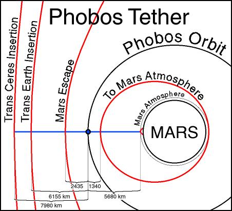
Evidently reaching a certain altitude is not the same as orbital insertion. And I never claimed that a SpaceShaft can do such a thing, but neither can do it the CNT tether. Both systems are only capable of assisting in the launch of spacecraft. The CNT tether gives the impression that it will release spacecrafts at GEO altitude. What this means is that a spacecraft at this altitude will still need to navigate away from the GEO station. Besides the high traffic of junk being incremented, there is still the needed independent maneuvers by the spacecraft to home towards other orbital regions. And any cargo meant to be brought back to Earth will require the spacecraft to go back to those predefined stations. In the case of a SpaceShaft, the launching and landing can happen at altitude regions where there is less traffic and with little amount of needed energy for orbital insertions by the spacecraft. And this without taking into account the safety fact that a SpaceShaft cannot fall back to the planet surface because is a buoyant structure.

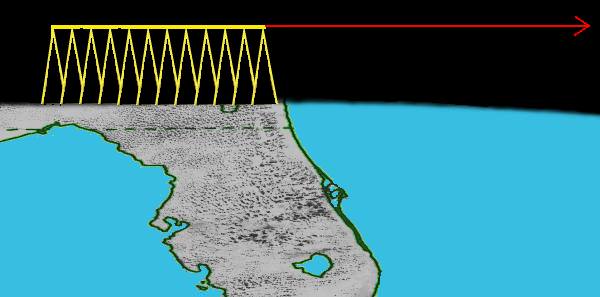
Consider the following: The shuttle/ISS only goes up to a max of about 400 km. In fact any other rocket, (and also so the shuttle,) uses its first stage just to travel to an altitude of 100 km, perpendicular to Earth's surface. After consuming all the fuel and the release of the tanks and engines, (of the first stage,) it is inertia that takes over and keeps aloft the remaining mass, (payload, second stage, etc.). Until the next propulsion blast from the 2nd stage happens. As said all this happens at just an altitude of about the Karman line, you can call this the freefall intermezzo, during which the max upward velocity is a meager 100 to 300 km/hr, (depending on the model and maker,) and for a few seconds, the rocket is moving upwards only due to diminishing inertia. But it is during this time that it has to maneuver to get the inclination needed as to fire the next engine, i.e. 2nd stage, which is intended to produce the tangential velocity for orbital insertion.

Very much as this 1st stage upthrust is what brings the rocket into position for orbital insertion, so can a SpaceShaft elevate a small/medium size rocket into space and so providing very unexpensively the altitude for an assisted launch. Include to the list of applications; touristic gliders (like Virgin's SpaceShipTwo), microsatelites (and satellites), or even landings from orbital spacecrafts. One thing the regular CNT tether cannot offer are high atmospheric facilities which would house human researchers. Other noticeable properties is that the system is transportable something the CNT tether is not.

With what I wrote here I may not have been as clear as I would have liked to be, but I hope it has been clear enough. I will insist you study the designs I've made and are found at the website (http://spaceshaft.org). There is one drawing in which cube-like balloons are attached to each other forming a sectional-ring of 36 units. Such ring is should be about 50 m in diameter totaling 3.6 tones of upthrust per ring at sea level. These rings are then stacked and are secured with inflatable beams, which are also buoyant and are intended to help in the structural toughness. These beams are somewhat like TensAirity beams, (see the reference section,) which provide a high resistance to bending/deflection.

References
Sphere volume: http://en.wikipedia.org/wiki/Sphere#Volume_of_a_sphere.
Mass of air at sea level: http://en.wikipedia.org/wiki/Atmosphere_of_Earth.
Barometric formula: http://en.wikipedia.org/wiki/Barometric_formula.
Center of Buoyancy: http://en.wikipedia.org/wiki/Center_of_buoyancy.
TensAirity: http://www.google.com/search?um=1&hl=en ... a=N&tab=iw

best regards
 
N

neilsox

Guest
On the early climbers the climber is wrapped around the ribbon. I presume a slot is necessary on one side so the climber can be put on the ribbon. If the climber slot can be opened on the correct side of both climbers then they can pass where the ribbon width is more than sum of the width of the two climbers. In fact the slot must be opened as there is not room for a double width ribbon, unless the ribbon can be folded in thirds = not likely. The slot can be closed again while the climber is on the side track if the side track method is used. To move from the side track back onto the main ribbon, the climber must make the move with the slot opened. Even one slot weakens the climber significantly. Slots on both sides that can be opened, greatly weakens the climber, requiring much extra weight to make sure both slots are not opened as the two halves of the climber would fall off the ribbon if both were opened due to an error. Extra weight in the climber construction subtracts from the pay load, and/or the max speed and/or the climber may break in half. Neil
 
E

EarthlingX

Guest
spacecoalition.com : Space Elevator for the Moon Proposed
July 12, 2010


Credit: LiftPort Group

It is not science fiction. It’s a way to colonize space using today’s technologies and materials.

That’s the view of advocates for planting a space elevator on the Moon. The concept would consist of a ribbon made of very strong and very light material — carbon nanotubes being a material of choice – stretching out from the lunar surface into space.

Once in place, elevator cars serve as robotic lifters to haul cargo. Such a lunar elevator could provide cheap and reliable access to the Moon.

In order to fine tune the plan, the LiftPort Group of Bremerton, Washington is holding a workshop dedicated to realizing the Lunar Elevator in the next 10 years. The event is being held July 31 – August 1 at the Future of Flight museum in Everett, Washington.

The LiftPort Group goal is to create a scalable, mass space transportation system, open up the vast market opportunities that exist in space, many of which haven’t even been imagined yet.

For information on the Lunar Elevator workshop, go to:

http://www.spaceelevatorevents.com/index.html

By Leonard David
 
G

global_lift

Guest
I feel that most of the graphics that try to put forward the concept of the Centrifugal CNT Space Elevator give an erroneous idea of the distances that need to be covered by the technology. Therefore giving the wrong impression of how near/away the distances are and how difficult everything everything would be.

This image tries to put the distances in true perspective, although still very imperfect due to the limited surface of a US Letter Size paper or an EU A4. I've tried to respect the proportionality of distances and not on objects other than Earth and the Moon.

20100803-1_orbitalMechanics.jpg


the pdf version can be downloaded here http://spaceshaft.org/images/20100803-1_orbitalMechanics.pdf

The image below represent distances 1/2 of those shown above, there are some simplified formulae related to orbital mechanics of satellites clutterering the page but they are also useful for reference.

20100803_orbitalMechanics.jpg


the pdf version can be downloaded here http://spaceshaft.org/images/20100803_orbitalMechanics.pdf

A SpaceShaft although not as ambitious as the Centrifugal CNT Tether Space Elevator could provide access to LEO and high atmospheric altitudes, both being regions that are by far more important economically to human habitants than GEO. Take into consideration where spaceplanes are to operate, space energy can more readily be obtained without the risks of power beaming, or CO2 sequestration from the atmosphere could be implemented, and these are just a few examples.

N. Semino
SpaceShaft/GlobalLift


EarthlingX":395kqtav said:
spacecoalition.com : Space Elevator for the Moon Proposed
July 12, 2010


Credit: LiftPort Group

It is not science fiction. It’s a way to colonize space using today’s technologies and materials.

That’s the view of advocates for planting a space elevator on the Moon. The concept would consist of a ribbon made of very strong and very light material — carbon nanotubes being a material of choice – stretching out from the lunar surface into space.

Once in place, elevator cars serve as robotic lifters to haul cargo. Such a lunar elevator could provide cheap and reliable access to the Moon.

In order to fine tune the plan, the LiftPort Group of Bremerton, Washington is holding a workshop dedicated to realizing the Lunar Elevator in the next 10 years. The event is being held July 31 – August 1 at the Future of Flight museum in Everett, Washington.

The LiftPort Group goal is to create a scalable, mass space transportation system, open up the vast market opportunities that exist in space, many of which haven’t even been imagined yet.

For information on the Lunar Elevator workshop, go to:

http://www.spaceelevatorevents.com/index.html

By Leonard David
 
S

samkent

Guest
With all the math and design concepts, these ideas of cables and nano tubes dangling down to the Earth are fine until the ISS comes by and snags it.

As for us not using one on the Moon? We don’t need it.
 
G

global_lift

Guest
samkent":108bpyu6 said:
With all the math and design concepts, these ideas of cables and nano tubes dangling down to the Earth are fine until the ISS comes by and snags it.

As for us not using one on the Moon? We don’t need it.

I like your humorous remark but let me have a go to it as well.

Such an event could happen to any building, city or individual passing by.

By now you must have realized that the theoretical Centrifugally Extended CNT Tether Space Elevator has received a lot of public attention thanks to a lot of publicity. One thing that is not know and people do not realize is that there is a reason for it.

Basically by means of encouraging popular inventiveness; patent holders can get cheap labor for the development of technologies that may be suitable for even other applications than the elevator itself even if it is never built.

Most of the famous guys involved in the competitions have such patents and the competitors are the cheap labor.

Cheers :)
 
E

EarthlingX

Guest
A couple of very nice links and comments worth reading in this article:

http://www.universetoday.com : Astronomy Without A Telescope – Space Towers
Sep. 4th 2010
by Steve Nerlich

9AlPZZ3iiR5U1Rk2hx.jpg

The Seattle space needle pokes through the cloud tops (well, just fog really… it's only 184 meters high). Credit: Liem Bahneman, pixduas.com

Arthur C Clarke allegedly said that the space elevator would be built fifty years after people stopped laughing. The first space tower though… well, that might need a hundred years. The idea of raising a structure from the ground up to 100 kilometers in height seems more than a bit implausible by today's engineering standards, given that we are yet to build anything that is more than one kilometer in height. The idea that we could build something up to geosynchronous orbit at 36,000 kilometers in height is just plain LOL… isn't it?

tower2.jpg

An inflatable 100 kilometer high, 300 kilometer long space pier, built to launch spacecraft horizontally. Humans might survive the G forces required to achieve orbit - which they certainly wouldn't do if the same trajectory was attempted from sea-level. Credit: Josh Hall, autogeny.org/tower/tower.html


Further reading: Krinker, M. (2010) Review of new concepts, ideas and innovations in space towers. (Have to say this review reads like a cut and paste job from a number of not-very-well-translated-from-Russian articles – but the diagrams are, if not plausible, at least comprehensible).

Book, available for on-line reading, found among references in the above paper :
www.scribd.com : Alexander Bolonkin, Non-Rocket Space Launch and Flight
 
M

MeteorWayne

Guest
Yeah, like we could afford to build such a structure...
 
Status
Not open for further replies.

Latest posts